
When I was a kid, we went to a 50’s diner (Hey I was a kid in the 80’s I’m not all that old) and I loved the jukebox , and the table top control box known as a wallbox. In this retro-electronics refurbishment, we transform an old wallbox, into a raspberry-pi powered Music powerhouse. While I would love to have a full size jukebox, we just don’t have the space in our small house. This project took about two weekends to complete, and only had a few minor hiccups. In this project will be using 25 volts AC, which is enough to give you a small shock, and 120V AC which can give you a substantial shock. Be sure To use electrical safety!
The first thing you’ll need, is a wall box. I purchased mine on eBay for about $100 including shipping, although the price varies widely depending on the condition and the current market. This project is going to use the original circuitry of the wall box, so if you can get one in working condition that will make your life easier. If you want you can even have the coin box still operating and make some money off the project if you run a bar; however, If you want everything to fit inside the wallbox, you’ll have to give up the coin-rejector and coin box.
Total Parts List (Links go to where I purchased):
1 – Seeburg Wall-O-Matic 100 or 200 (They are often on eBay in the $100 range. )
1 – Raspberry Pi (any model, I used the A initially, and upgraded to a 2)
—— Wireless or Wired network adapter for debugging or Sonos/remote play
1 – 120V (or 240V if that’s your countries power) to 25V-AC (NOT DC!) transformer ( I used a HM556-ND transformer from Digi-Key)
1 – 120V (or 240V as above) to 5V-DC USB converter rated for at least 2-2.5A (I use this one )
1 – Rectifier – I used a 2W005G-E4 rated for 2A @ 50V plenty of headroom (recall that on 25V AC waveform the max voltage is actually 35.36V at the peak of the wave)
1 – Voltage Regulator ( KA78R33CTUFS-ND)
1 – Optio-isolator (optional, but saved my pi, I blew up one pi, They are 10 for $5 at Amazon)
1 – LED (optional, lets you know box is sending signals)
2 – 5 Amp fuses (optional, but saved my wallbox)
1 – small piece of breadboard to keep things nice
Assorted resistors. I used a 1M-ohm between signal and ground to pull down some stray voltages.
Some conformal coating and hot glue to isolate and hold everything together. The first link is for Amazon, see our page talking about conformal coating here.
General Idea
Here is an overview video of the project:
The seeburg wall box was meant to be used as a remote to a main jukebox. This was made in the era before solid-state and digital transmission, and uses a clever pulse train to physically activate switches in the main jukebox. We want to take these old school 25V AC pulses, turn them into 5V DC pulses, and then read them with a Raspberry Pi. Once you have the track letter and number in your raspberry pi, you can do whatever you like! I use them to do several things. Some play single tracks of music, some play a streaming online station, and yet others control my lights and stereo, but that’s another post.
First off to power the wallbox you need a 25V AC transformer, why AC? Remember we aren’t in your fancy modern age with solid state devices, we’re just changing the voltage from the mains. Like I mentioned above the unit sends out pulses corresponding to the number and letter pushed on the front. Now 25V AC pulses would make quick work of our Pi (as I found out via smoke and a lost $25 board). We want to convert them first to DC, and then lower the voltage to 5V. This is accomplished via a rectifier, and a voltage regulator. Now this won’t be a true solid square wave of pulses, because when the AC current goes between -3.5 and 3.5V, the voltage converter will output 0V; however, this is ok and we can filter it out in our software.
Now that we have a nice 5V DC signal, we simply put that into a GPIO pin on our minicomputer, and head over to software land.
I used python based off of someone who had done something similar (Here is his site (now on the wayback)) It monitors for the first pulse, then counts the number of pulses, a pause, and some more pulses. See more in the details. Once we have counted the two pulse trains, we have the letter and number of the buttons pushed!
At this point you can do several things, if you want to use the minicomputers audio out, you can run a script to play an audio file off the local storage, or play an internet stream off the network. Really you shouldn’t think of your wall-o-matic as a jukebox accessorry any more, and more like a giant remote control with 100 or 200 selections.
In my first iteration I left the wallbox itself 100% unmodified, and hooked up power and the signal line to a small plastix box which contained my pi, transformer, and signal converting circuit. In the second go around, I placed all of this inside the wallbox so that it’s a neat contained unit with just a 110V AC cord coming out.
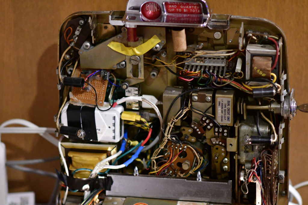
The Wallbox with the pi, 25V AC transformer, bread board, and old USB power
On to the Details!
1. The first thing to do is open up the wallbox, luckily the original repair manual is still available!
If you’re unit has the key, turn it and slide the cover off, I find that pushing in the middle of the buttons helps. A good video overview of the wallbox is available here: video of seeburg wallbox working . You can also search on youtube for your specific model.
For the purpose of this article, I’m going to assume you have a fully functioning wallbox. If you are looking to put everything external, all you need to do is supply 25V Ac to the power terminals, and run a common and signal line out to you external box. If that’s the case, do that, button up your wallbox and put it aside, skip to step 2!
If you want to make a self contained unit, remove the coin box from the lower right backhand side, and remove the coin rejector unit. A working coin rejector unit can fetch you about $30 on ebay, so don’t trash it! Now you have lots of empty space, I placed my 25V Ac transformer in the coin rejector area, topped with a 110V to USB adapter, and the raspberry pi in front of that. It all fits pretty well. You can figure out how your particular parts fit best.
But! Everything in here it metal I hear you saying, I need to be super carefull on where to put my pi! That’s true, but there is a cure. Conformal coating is a spray on urethane specifically designed for this purpose. It’s cheap (about $11 from Amazon ). Plug in something to every port you ever want to use on the PI (because any open port will be covered, and electrically nonconductive, and therefore not useable) and give it a good coating. I still try to ensure traces are touching metal, but this coating will give you a great insurance policy.
1.1 The electrics! I started with the well written info from this Wallbox Controller (now on wayback) site. It had an awesome description and graphics of the signals you’d see; however, it didn’t 100% work for me out of the box. I made a few improvements on the design.
Fuses, Fuses, Fuses! Why is worth saying 3 times? Any maker who has been around the block will have a story of some time they “let the smoke out” of an important piece of equipment. I almost let it out of my wallbox when a direct short threatened to almost destroy everything (luckily a 15 amp breaker on my power strip saved me). I used two fuses, one 3A fast blow on the 100V AC input (120V in the US, 240V in Europe and others) and one 5A slow blow on the output of the 25V transformer. The 3A fast blow means that any dead short in the USB power supply or transformer will be relieved within a few cycles. The wallbox is rated at 3A, but being all analog and motors, spikes are likely. the 5A slow blow provides a good range of protection, and won’t accidentally pop on a stuck contact.
New Fangled Digital doesn’t like old fangled Analog!: The design on the weebly site connects the pi directly to the wallbox via a voltage regulator. He used a significantly newer model than I did, so it was maybe fine, but on mine there was all kinds of leakage current and spikes. I destroyed a Pi A on my first attempt from high voltage blowing up the CPU. Luckily there exists a cheap device for just such a problem, 10 of them cost US$2.50 here on Amazon, the opto coupler. This device is simple, on one side you have a device sendings signals, these signals drive an LED which gets brighter or dimmer depending on the input. The other side is hooked to a phototransistor, which will pass more or less voltage depending on the brightness it sees.
Both are electrically isolated from each other. The only connection is the light that passes between them. They are packaged in a single IC for just this kind of purpose. Even if you had a spike of 1000V on the input side, the worst it could do was make the phototransistor 100% pass thru for the output side, which we are prepared for. This completely isolates one system from another. You will see these used in all kinds of digital signaling where grounds may be at different potentials, or spikes are common or expected. It’s extremely cheap for the insurance.
Ok ready to wire!: Now that you have the basic ideas, hooking everything together isn’t so touch. The signal flow is going to come from the terminals of the wallbox and proceed as follows:
Wallbox Terminals -> Rectifier -> Voltage regulator -> optical isolator -> Raspberry Pi
|-> LED (optional, lets you know the rest of the circuit is working)
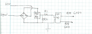
Wallbox Schematic
…
2. Software
All of the software is written in python 2. While python 3 seems to be up and coming, the majority of the current modules are written for Python 2. My software is not elegant. It scans thru a file line by line until it find the entry you pressed. Keep in mind that this will be at most 200 entries, and even the Raspberry Pi A’s complete this task in micro-seconds. Given that the wallbox itself will take over a full second to complete sending, I didn’t bother to optimize this code in the least!
The current code is located at GitHub Here: https://github.com/CottonThePirate/wallboxController
Please report bugs, as I use a different code in my day-to-day that has some additional Hue light options.
I have a Sonos brand whole house audio solution, it’s expensive, the cheapest speaker, a Sonos 1 (Amazon Link) costs $200. That being said it’s bullet proof. The API is open, and I use the Soco Controller (github link) to control it. The examples are tuned towards that application, if you want to use the Pi’s audio out, or another streaming solution, be sure to post it in the comments!
So here is the basic flow of the software:
-
- Monitor the GPIO in a constant loop
- Interrupt may be faster, but this uses less than 20% of the Pis time.
- Monitor the GPIO in a constant loop
-
- When a signal is seen on the GPIO pin, read all the pulses
- Filtering out the 60Hz (or 50Hz) AC dips from the voltage regualtor
- When a signal is seen on the GPIO pin, read all the pulses
-
- After the pulses stop you have a track letter and number
-
- Read the .csv file and go util you hit that letter and number
-
- Perform various actions depending on the instructions in the .csv
- I have my wallbox set up to control sound (sonos), lights (phillips hue), and system control (reboot Pi, etc)
- Perform various actions depending on the instructions in the .csv
- Go back to 1
3. Configuring stations and playlists
When I originally bought my Wall-O-Matic 200 off ebay, I was sure to try and find a 200, vs a 100, so that I would have enough slots for all the songs I wanted! Turns out this wasn’t the problem I thought it’d be, as it’s hard to come up with 200 songs and stations that I wanted on my Wallbox. I have thousands of songs, but not that many that I want to access from my wallbox. We actually came up with only about 50 actions. The software reads a Comma Separated Value (.csv) file. This file is an export option on all spreadsheet programs. It is what it says it is, a plain text file where each line has entries separated by a comma.
4. Printing Labels
There are a few programs out there that can help you print out awesome looking labels. One of the best I’ve found online is at Mike’s Arcade Website . It’s also a great source for various video game and jukebox parts. I print them out in color on matte photo paper. His site lets you choose from a bunch of cool designs.
5. Enjoying your Wallbox!
6. Ideas for future improvements
Obviously this page is still a work in progress, if you want some help with a project you’re working on give me an email! or leave a comment.
What does the schematic of the board look like?
Hi Andy, Are you asking about the board that converts the 25VAC signal to DC? I’ll try to draw it out in the next few days and add it!
The article has been updated with a schematic!
Where would I supply the 120 if og transformer still intact?.
Hi Shannon, Don’t hook up 120 to the Wallbox anywhere! It was originally meant to run on 25V AC from a Seeburg Jukebox. There is a small transformer inside to take this down to 6V to run the mini-light bulbs.
Hi, I have just seen your wallbox to mp3 project and must say it is fantastic!, I have been out today and bought a raspberry pi as it has inspired me. I have a 3w1 wallbox and would love to be able to do the same thing where the pi can select and play mp3 files. I have managed to build a rectifier circuit with a regulator which steps down the voltage to 3.3 v .I am new to the Pi and programming, but have managed to get a c program running that decodes the pulses (80% of the time). Please would you share with me your program to make the mp3 selection from the pulses as i can’t find any other help online. Thank you for taking the time to read this,
Kind Regards,
Jarrett
Hi,
My code is now posted, although I’m still debugging the public version
Hi,
I’m totally new in working with raspberry or even programming.
As I had the opportunity to purchase a seeburg 3W1 wall box, i’m interested to get it working on my sonos speakers.
Currently I have installed NOOBS Raspbian Stretch on the PI.
then installed the SoCo controller followed by the installation of your code.
Before I start making any hardware, I would like to see that the Sonos part is working.
but how can I test that it is working.
For example simulate button pressed . Ex A3. (whet do I modify the code?)
where do I set the IP adress of my sonos speaker(s) ?
How do I modify the database- changing track names ….
Hope you can give me more details or guide me through this process.
When I run the program “wallbox.py” i’m getting this error.
File “wallbox.py”, line 136
except: Exception, err:
^
SyntaxError: invalid syntax
forgive me for all these stupid silly questions, but I still have a lot to learn.
thx.
Johan
Hi – thanks for this, it’s given me a lot to look into.
Just a point to clarify – at one point you note that you don’t know who to credit for the software, then later on you link to your original inspiration for the controller hardware. It appears that this is the same person that wrote the original pulse monitoring software.
Currently rewriting your code to link to MPD installed on the Pi, with the eventual plan to have the controller as a small box on the hi-fi. A 200 song playlist on MPD could handle the wallbox’s output, but adding a web client also means it can play other music and internet radio. This could fairly easily index files on a server and play over wi-fi.
This is fabulous. Will the program work on a Seeburg SCI 1 Consolette?
Hi Mike, sorry for the delay. I think that it will, perhaps with some modification to the timing.
The program will work except the numbers and letters need to be swapped, and reversed, counting down instead of up (V1 is 1 pulse L/N gap and 8 pulses,V8 is 1 pulse, gap, 1 pulse, A1 is 20 pulses gap 8 pulses.Timings are close.
I also had some problems with Exception, err also, but re wrote some of the program to remove them.
Hi Mike,
I am new to the to the Pi Zero w and and python, I have an emulator running until the Pi arrives.
How do you run the code that is published?
I will also have to use the GPIO for audio out, as the Zero has only HDMI audio out.
It’s going to be a steep learning curve for me.
Is there any output to the console from the program?
Completed my conversion here on a Seeburg SCH1 with built in stereo speakers
https://www.audiokarma.org/forums/index.php?threads/seeburg-consolette-mp3-conversion-rasperry-pi-zero-w.889024/#post-13173629
Details in that thread, as well as program files and schematics
I’m definitely going to give this a try, it’s fascinating! Thanks for all the info😃
Hello. Will this work with a sound leisure wall box
In theory something similar could work. The pulses from the switch selections would almost certainly be different and require different timing. You should be able to use all the code except that part that decodes the button presses. I’ve never seen the inside of a sound leisure in person so I can’t be sure.
Could this be modified to send the signal to another rasp pi inside a jukebox so it can be used as a wireless remote for an old seeburg?
Hi, The answer is always yes, but how much work. The wall box sends a series of pulses that we decode to play a digital music file. I see no reason why you couldn’t send the decoded letter/number (Play B4 for example) to another unit inside a main jukebox. You would then need a similar circuit to recreate the weird (to 2022 eyes) AC pulse train. I’ve never played with a full size jukebox, but I understand they have a similar transformer already in them, so it’s probably as “simple” as using a transistor switch (controlled from an opto-isolated pi) to recreate the signal.
I know it’s an old post, but the answer is yes, it wouldn’t be hard, just write the selection to a text file, and ftp it into the Queue on the jukebox, , the queue can be read by the Pi, ane the letter / number combo can be written to the buttons on the machine with relays